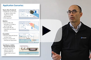
Evaluating the Longevity of a PFAS In Situ Colloidal Activated Carbon Remedy
Longevity of Colloidal Activated Carbon for In Situ PFAS Remediation at AFFF-Contaminated Airport Sites
Monitored Natural Attenuation to Manage PFAS Plumes in Groundwater: Potential Guidelines
Enhanced Attenuation (EA) to Manage PFAS Plumes in Groundwater
PetroFix Direct Push Injection Planning

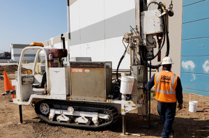
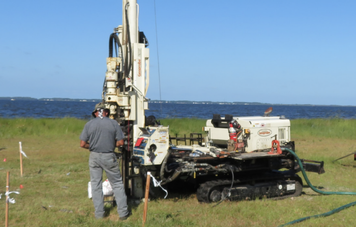
Please follow the specific handling, injection tips, and field distribution verification steps recommended. Examples include having long, multi-port injection tips and budgeting a few hours for Day 1 field distribution observation and adjustments. Please review:

In addition to best practices addressed in the “Pre-Application” planning resources, it is recommended you review the available application instructions. Some practitioners opt for a clear water post-injection flush at the end of their injection activities.

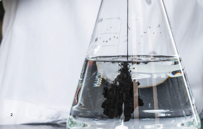
Please note, PetroFix takes up to a few months to fully attach to soils. If PetroFix is >100 mg/L in concentration (difficult to see through a 40 ml VOA), it is recommended groundwater not be sampled. Each PetroFix shipment comes with one (1) a colorimetric field test kit taped to the top of a tote or drum to help assess field concentrations. For additional information, please review the “Groundwater Sampling Guidance Document”.
PetroFix Excavation Planning

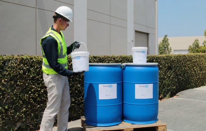
When storing the PetroFix material prior to application, it is important to prevent it from freezing or from prolonged exposure to temperatures above 95°F.

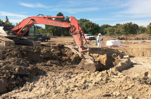
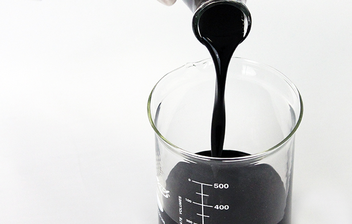
In most cases, PetroFix is spray applied to the base of an excavation following soil removal. Prior to spray-applying the material, PetroFix should be diluted with water. Determine the amount of dilution based on the ability to safely spray and fully coat the base and sidewalls of the excavation. Larger excavations tend to require more dilution water (2:1 dilution or higher) for the spray “reach” into the excavation. A suggested dilution is provided on your output page, but modify as needed.

PetroFix material can reach nearby wells outside of the application area (usually a few feet away) following injection or into newly installed wells in your excavation location. Please note, PetroFix can take up to a few months to fully attach to soils. If PetroFix is observed in wells >100mg/L in concentration, it is recommended groundwater not be sampled (difficult to see through a 40 ml VOA). Each PetroFix shipment comes with one (1) colorimetric field test kit taped to the top of the tote or drum to help assess field concentrations. For more information, please review the “Groundwater Sampling Guidance Document”.
PetroFix Well Injection Planning

When storing the PetroFix material prior to application, it is important to prevent it from freezing or from prolonged exposure to temperatures above 95°F.

The key to a successful well application is to have properly screened wells where the screen is confined across your treatment zones only. We recommend you use a water tight injection attachment to the top of your well and apply PetroFix under low pressure (commonly 20-30 psi). Optimally, you can construct your monitoring wells with a male NPT thread so receive a female threaded injection hose adapter. If you are using existing injection wells you can use ratchet straps that prevents gluing any attachments fittings to a well. Please consult with your injection contractor for their recommended method to inject into your monitoring well(s). Flushing by gravity feed into wells is not recommended. When complete some practitioners opt for a clear water post-injection flush at the end of their injection activities. If your site has a high number of wells we recommend that you install a single well and do a pilot injection prior to full-scale implementation to verify the ability to inject PetroFix at the specified volumes.

Please note, PetroFix takes up to a few months to fully attach to soils. If PetroFix is >100 mg/L in concentration (difficult to see through a 40 ml VOA), it is recommended groundwater not be sampled. Each PetroFix shipment comes with one (1) a colorimetric field test kit taped to the top of a tote or drum to help assess field concentrations. For additional information, please review the “Groundwater Sampling Guidance Document”.
Remediation Journal Article on Enhanced Natural Attenuation for PFAS, Volume 32, Issue 3 – Summer 2022
 A recent paper entitled “Enhanced attenuation (EA) to manage PFAS plumes in groundwater”, authored by a very credible group of individuals from GSI Environmental and recently published on the REMEDIATION Journal website (the article is open access, meaning anyone can access it for free, and it is to be included in the Fall publication of REMEDIATION Journal). This paper follows two other publications by the same group1, 2 that were supported by ESTCP funding which set the groundwork for the technical argument supporting the use of natural attenuation as a remedial strategy for treating PFAS in groundwater.
Key takeaways:
- Enhancing PFAS retention can play a key role in reducing mass This can result in the following plume management benefits:
- Plume Retention processes can slow the migration of PFAS extending the time before a plume impacts a receptor.
- Peak shaving or Peak Some retention processes can result in the blunting of a short-term, high mass discharge plume, converting it to a longer term but low mass discharge plume. In this case, the peak concentration of PFAS in water is decreased due to the rate of adsorption being faster than the rate of desorption. (See Figure 3 in the paper for a visualization of this.)
- Plume At some sites, increasing PFAS retention along with dispersion may be enough to stabilize a plume and prevent further expansion.
- Plume If the source has been removed and the plume stabilized, over time it may shrink.
- Eight Methods to Enhance Retention of PFAS are reviewed or hypothesized:
- Injection of particulate This is a direct acknowledgement of REGENESIS’ success at using PlumeStop®to treat PFAS plumes and is mentioned as currently being practiced. This method is noted as having among the highest retention and in current practice.
- Capping of source This is cited as a method to retain PFAS mass in the vadose zone.
- Gas This is a hypothesized method of concentrating PFAS at the groundwater table in an effort to retain PFAS.
- Salting out This again is a hypothesized method of adding ionic strength to reduce the solubility of PFAS.
- Placement of vertical columns of sorbent. Use of heavy geotechnical equipment to drive or drill borings that are then filled with slurry of
- Emplacement of oil at groundwater This hypothesized approach would collect PFAS at the water table in an LNAPL of food grade oil.
- Use of emulsified vegetable oil to enhance Injection of emulsified oil to keep an aquifer anaerobic and limit aerobic biotransformation of precursors, and offer added retention of PFAS similar to a sorbent.
- PFAS discharge to surface water+ This hypothesized approach is to build walls to funnel all migrating PFAS in groundwater to surface water, then sparge water to collect PFAS in oil layer.
Summary
This paper acknowledges that the injection of sorbents can result in high PFAS retention and reduction in mass flux. The paper points out that such retention of PFAS “fits directly into the enhanced attenuation framework, an established groundwater remediation strategy that was developed in the first decade of the 2000s for other groundwater contaminants”. This enhanced retention, particularly in combination with source capping or removal, can result in plume retardation, plume stabilization and plume shrinking.
Among the eight methods cited to enhance natural attenuation through PFAS retention, only the injection of particulate sorbents (PlumeStop) is noted as increasing the retention of PFAS and currently being practiced. Capping of the source zone is the only other method currently being implemented at PFAS sites, while the other six are unverified, early-stage concepts.
1 Newell, C.J., Adamson, D.T., Kulkarni, P.R., Nzeribe, B. N., Connor J. A., Popovic, J., & Stroo, H. F. (2021). Monitored natural attenuation to manage PFAS impacts to groundwater: Scientific basis. Groundwater Monitoring& Remediation, 41(4), 76-89. https://doi.org/10.1111/gwmr.12486
2 Newell, C.J., Adamson, D.T., Kulkarni, P.R., Nzeribe, B.N., Connor, J.A., Popvic, J., & Stroo, H. F. (2021). Monitored natural attenuation to manage PLFAS impacts to groundwater: Potential guidelines. Remediation Journal, n/a, 31, 7-17. https://doi.org/10.1002/rem.21679
PetroFix Technical Information
Application Instructions
Technical Bulletins
Product Literature
Safety Data Sheets
Design Tools
HRC, HRC-X and 3-D Microemulsion Application Instructions
HRC Application Instructions
Hydrogen Release Compound (HRC®) can be applied to the subsurface in a number of different ways. The application method chosen is often attributed to a range of factors including depth to groundwater, soil type, location and extent of contaminants, remediation objective, etc. Typical installation of HRC involves the use of direct-push technology which can be an extremely cost-effective, efficient and clean way to deliver the product into groundwater. The following table contains HRC installation instructions for several different types of installations. HRC is typically applied using direct-injection techniques. This process enables the viscous HRC material to be pressure injected into the zone of contamination and moved out into the aquifer media. Once in the subsurface, HRC can reside within the soil matrix fueling reductive dechlorination and promoting reducing aquifer conditions for periods of up to 24 months or longer through the controlled release of lactic acid and subsequent hydrogen production.
For details related to HRC application please refer to the detailed instructions below.
HRC-X Application Instructions
Extended – Hydrogen Release Compound (HRC-X)® is a special formulation of the patented and widely accepted Hydrogen Release Compound (HRC) which has been successfully installed on hundreds of project sites world-wide. It is specifically formulated to treat residual dense non-aqueous phase liquids (DNAPL) in the groundwater and provide a long-term solution to groundwater plume control. HRC-X is manufactured as a viscous gel that can be injected into the saturated zone in a grid- or barrier-based configuration for either localised area or cutoff-based treatment approaches. Regenesis believes that the best method to install HRC-X into the subsurface is using direct-push drilling techniques. This method allows for the product to be pushed into the formation instantly and provides greater coverage/treatment over the life of the product.
For details related to HRC-X application please refer to the detailed instructions below.
3-D Microemulsion Application Instructions
3-D Microemulsion (3DME) is typically applied in high-volumes as an emulsified, micellar suspension (microemulsion). 3DME comes as a concentrate, which requires emulsification and dilution prior to injection. 3DME Factory Emulsified is delivered to site pre-emulsified and only needs dilution for even easier application.
The microemulsion has a relatively high hydrophilic/lipophilic balance (HLB). This high HLB allows dilute 3-D Microemulsion suspensions to be well distributed across contaminant plumes without high injection costs. 3-D Microemulsion applications can be configured in several different ways including: grids, barriers and excavations. The material itself can be applied to the subsurface through the use of direct-push injection, hollow-stem auger, existing wells or re-injection wells 3-D Microemulsion is usually applied throughout the entire vertical thickness of the determined treatment area. Once injected, the emulsified material moves out into the subsurface pore spaces forming micelles and moving via micellar transport, eventually coating most all available surfaces, these structures provide the added benefit of increased distribution via migration to areas of lower concentration. Over time the released soluble components of 3-D Microemulsion are distributed within the aquifer via the physical process of advection and the concentration driven forces of diffusion.
For details related to 3-D Microemulsion on-site emulsification and application please refer to the detailed instructions on right side.

 Americas
 Europe
 Français
 Deutsch
 Italiano
 Español
