Americas
 Europe
 Français
 Deutsch
 Italiano
 Español
Proven PFAS Remediation Technology Promises to Save Billions in Project Cost

Published Research of US Air Force Base Shows Potential for Over 60% Savings
Too often the US Department of Defense (DoD) contractors default to the installation of pump and treat systems to mitigate PFAS pollution in groundwater. This approach has been proven inefficient and will not flush the aquifer free of PFAS. It serves only as a plume containment strategy. The use of in-ground colloidal activated carbon filtration (in situ CAC filtration) is a proven PFAS remediation approach. It presents a much more cost-effective and resilient solution, while avoiding the liability and long-term risk of PFAS waste. Where appropriate, in situ CAC filtration has the potential to reduce the DoD PFAS-related environmental liability by billions of dollars over the next 30+ years.
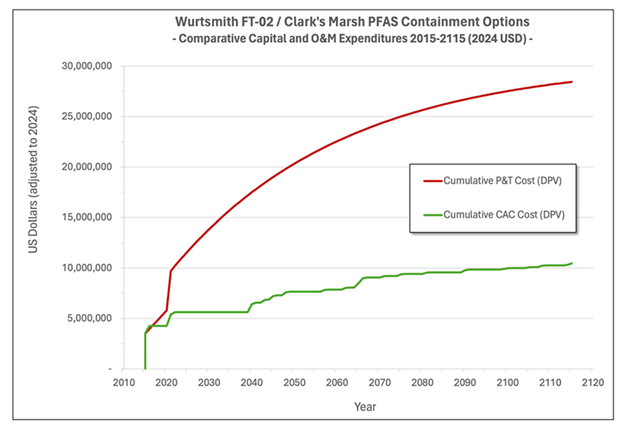
Recognized remediation experts Jeremy Birnstingl1, and John Wilson2 recently published a research paper entitled A Cost Comparison of Pump-and-Treat and In Situ Colloidal Activated Carbon for PFAS Plume Management3. The research discloses the high cost the DoD is paying to contain a PFAS plume at an existing DoD installation employing a typical pump and treat approach. Further, the paper compares the costs of operating the current remediation system with the costs of installing and operating an in situ CAC filtration system.
Key Takeaways:
- Pump and Treat will not flush PFAS from the aquifer – even after 100+ years of pumping.
- Over 60% Cost Savings – For the subject site, in situ CAC filtration was shown to be about 1/3 the cost of pump and treat systems over a 30-year period ($7.2M vs $19M)
Other Considerations:
- Zero Waste – Unlike pump and treat systems that generate hazardous PFAS waste, in situ CAC filtration generates no waste
- Reduces Risk and Liability – In situ CAC filtration eliminates the need to transport PFAS waste generated through public streets to a hazardous waste disposal facility and risking future liability
- No Energy or O&M Required – In situ CAC filtration effectively contains the PFAS plume while requiring no energy input or on-going operation and maintenance
- Jeremy Birnstingl, PhD, Regenesis, Bath UK
- John Wilson, PhD, Scissortail Environmental Solutions, Ada OK USA (formerly USEPA, Kerr Research Center, Ada OK)
- “A Cost Comparison of Pump‐and‐Treat and In Situ Colloidal Activated Carbon for PFAS Plume Management” © 2024, Authors Birnstingl, Wilson. Remediation Journal, Published by Wiley Periodicals LLC
PetroFix Technical Information


HRC, HRC-X and 3-D Microemulsion Application Instructions
HRC Application Instructions
Hydrogen Release Compound (HRC®) can be applied to the subsurface in a number of different ways. The application method chosen is often attributed to a range of factors including depth to groundwater, soil type, location and extent of contaminants, remediation objective, etc. Typical installation of HRC involves the use of direct-push technology which can be an extremely cost-effective, efficient and clean way to deliver the product into groundwater. The following table contains HRC installation instructions for several different types of installations. HRC is typically applied using direct-injection techniques. This process enables the viscous HRC material to be pressure injected into the zone of contamination and moved out into the aquifer media. Once in the subsurface, HRC can reside within the soil matrix fueling reductive dechlorination and promoting reducing aquifer conditions for periods of up to 24 months or longer through the controlled release of lactic acid and subsequent hydrogen production.
For details related to HRC application please refer to the detailed instructions below.
HRC-X Application Instructions
Extended – Hydrogen Release Compound (HRC-X)® is a special formulation of the patented and widely accepted Hydrogen Release Compound (HRC) which has been successfully installed on hundreds of project sites world-wide. It is specifically formulated to treat residual dense non-aqueous phase liquids (DNAPL) in the groundwater and provide a long-term solution to groundwater plume control. HRC-X is manufactured as a viscous gel that can be injected into the saturated zone in a grid- or barrier-based configuration for either localised area or cutoff-based treatment approaches. Regenesis believes that the best method to install HRC-X into the subsurface is using direct-push drilling techniques. This method allows for the product to be pushed into the formation instantly and provides greater coverage/treatment over the life of the product.
For details related to HRC-X application please refer to the detailed instructions below.
3-D Microemulsion Application Instructions
3-D Microemulsion (3DME) is typically applied in high-volumes as an emulsified, micellar suspension (microemulsion). 3DME comes as a concentrate, which requires emulsification and dilution prior to injection. 3DME Factory Emulsified is delivered to site pre-emulsified and only needs dilution for even easier application.
The microemulsion has a relatively high hydrophilic/lipophilic balance (HLB). This high HLB allows dilute 3-D Microemulsion suspensions to be well distributed across contaminant plumes without high injection costs. 3-D Microemulsion applications can be configured in several different ways including: grids, barriers and excavations. The material itself can be applied to the subsurface through the use of direct-push injection, hollow-stem auger, existing wells or re-injection wells 3-D Microemulsion is usually applied throughout the entire vertical thickness of the determined treatment area. Once injected, the emulsified material moves out into the subsurface pore spaces forming micelles and moving via micellar transport, eventually coating most all available surfaces, these structures provide the added benefit of increased distribution via migration to areas of lower concentration. Over time the released soluble components of 3-D Microemulsion are distributed within the aquifer via the physical process of advection and the concentration driven forces of diffusion.
For details related to 3-D Microemulsion on-site emulsification and application please refer to the detailed instructions on right side.